
Wireless Notice Board is very selective term for this project, as it has a very wide scope rather than just being a simple notice board. First we should understand the purpose of this project, in this system we can display a message or notice to some display device like LCD, and this message can be easily set or changed from anywhere in the world, just by using the SMS Facility of your mobile handset. Whatever notice we want to display, just send the SMS of that text, with some prefix and suffix.
This is very useful in Hotels, Malls, college, offices and can be used anywhere, even at home. Like you can set the message like “Do not disturb” at your hotel’s room gate, can set message at your home’s door step when you are away, and of course it is used as notice board in schools, colleges, cinema halls etc. And yes, it’s just not a simple Message board, the usefulness of this project is that you can set or change the message or notice from anywhere, just sending SMS from your phone.
Working Explanation:
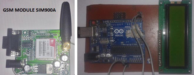
In this project, Arduino UNO is used for controlling the whole process, GSM Module (SIM900A) to receive the SMS/message sent from mobile phone and LCD to display the message.
We can send some message or notice like “#Circuit Digest*”, “#We Welcomes You*” through the SMS. Here we have used a prefix in the message string that is ‘#’. This prefix is used to identify the starting of the message or notice. And ‘*’ is used as suffix to indicate the end of the message or notice.
When we send SMS from mobile phone to GSM module then GSM receives that SMS and sends it to Arduino. Now Arduino read this SMS and extract main notice message from the received string and stores in another string. And then sends the extracted message to 16×2 LCD by using appropriate commands.
Further working of this system is explained in the ‘Code Description’ section below. Before we get into programming details we should know about GSM module.
GSM Module is used in many communication devices which are based on GSM (Global System for Mobile Communications) technology. It is used to interact with GSM network using a computer. GSM module only understands AT Commands, and can respond accordingly. The most basic command is “AT”, if GSM respond OK then it is working good otherwise it respond with “ERROR”. There are various AT commands like ATA for answer a call, ATD to dial a call, AT+CMGR to read the message, AT+CMGS to send the sms etc. AT commands should be followed by Carriage return i.e. \r (0D in hex), like “AT+CMGS\r”. We can use GSM module using these commands:
ATE0 For echo off
AT+CNMI=2,2,0,0,0 <ENTER> Auto opened message Receiving. (No need to open message)
ATD<Mobile Number>; <ENTER> making a call (ATD+919610126059;\r\n)
AT+CMGF=1 <ENTER> Selecting Text mode
AT+CMGS=”Mobile Number” <ENTER> Assigning recipient’s mobile number
>>Now we can write our message
>>After writing message
Ctrl+Z send message command (26 in decimal).
ENTER=0x0d in HEX
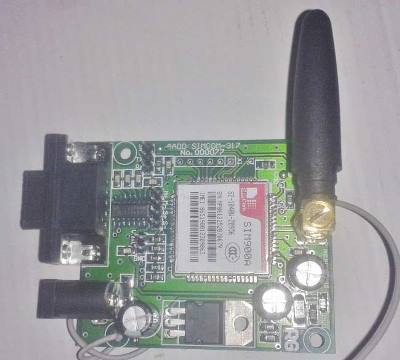
The SIM900 is a complete Quad-band GSM/GPRS Module which delivers GSM/GPRS 850/900/1800/1900MHz performance for voice, SMS and Data with low power consumption.
Circuit Description:
Connections of Wireless Notice Board Using GSM And Arduino are simple and shown in the figure below. Here a liquid crystal display (LCD) is used for display the “Notice” or message, which is sent though the mobile phone as SMS. Data pins of LCD namely RS, EN, D4, D5, D6, D7 are connected to arduino digital pin number 7, 6, 5, 4, 3, 2. And Rx and Tx pin of GSM module is directly connected at Tx and Rx pin of Arduino respectively. And GSM module is powered by using a 12 volt adaptor.

Code Description:
The code of the program is easily understandable; the new thing here is GSN Initialization function gsm_init(), which is explained in the end.
In the program, first of all we include library for liquid crystal display (LCD) and then we defines data and control pins for LCD and some variables.
#include <LiquidCrystal.h>
LiquidCrystal lcd(7,6,5,4,3,2);

int led=13;

int temp=0,i=0,x=0,k=0;
char str[100],msg[32];
After this, serial communication is initialized at 9600 bps and gives direction to used pin. And initialize GSM Module in setup loop.
void setup()
{
  lcd.begin(16,2);
  Serial.begin(9600);
  pinMode(led, OUTPUT);
  digitalWrite(led, HIGH);
  lcd.print("GSM Initilizing...");
  gsm_init();
  lcd.setCursor(0,0);
  lcd.print("Wireless Notice");
For receiving data serially we use two functions, one is Serial.available which checks any serial data is coming or not and other one is Serial.read which reads the data that comes serially.
void serialEvent()
{
  while(Serial.available())
  {
    char ch=(char)Serial.read();
    str[i++]=ch;
    if(ch == '*')
    {
      temp=1;
      lcd.clear();
      lcd.print("Message Received");
      delay(1000);
    }
  }
}
After receiving data serially, we store it in a string and this string is checked for ‘#’ and ‘*’, to find the starting and ending of the Notice or message. Then finally Notice is printed on LCD using lcd.print:
void loop()
{
  for(unsigned int t=0;t<60000;t++)
  {
    serialEvent();
  if(temp==1)
  {
    x=0,k=0,temp=0;
    while(x<i)
    {
      while(str[x]=='#')
      {
        x++;
        while(str[x]!='*')
        {
          msg[k++]=str[x++];
Initialization Function ‘Gsm_init()’ for GSM is important here, where firstly, GSM module is checked whether it is connected or not by sending ‘AT’ command to GSM module. If response OK is received, means it is ready. System keeps checking for the module until it becomes ready or until ‘OK’ is received. Then ECHO is turned off by sending the ATE0 command, otherwise GSM module will echo all the commands. Then finally Network availability is checked through the ‘AT+CPIN?’ command, if inserted card is SIM card and PIN is present, it gives the response +CPIN: READY. This is also check repeatedly until the network is found. This can be clearly understood by the Video below.
void gsm_init()
{
  lcd.clear();
  lcd.print("Finding Module..");
  boolean at_flag=1;
  while(at_flag)
  {
    Serial.println("AT");
    while(Serial.available()>0)
    {
      if(Serial.find("OK"))
      at_flag=0;
    }
    delay(1000);
  }
Code
#include <LiquidCrystal.h>
LiquidCrystal lcd(7,6,5,4,3,2);

int led=13;

int temp=0,i=0,x=0,k=0;
char str[100],msg[32];

void setup()
{
  lcd.begin(16,2);
  Serial.begin(9600);
  pinMode(led, OUTPUT);
  digitalWrite(led, HIGH);
  lcd.print(“GSM Initilizing…”);
  gsm_init();
  lcd.setCursor(0,0);
  lcd.print(“Wireless Notice”);
  lcd.setCursor(0,1);
  lcd.print(”    Board      “);
  delay(2000);
  lcd.clear();
  lcd.print(“Circuit Digest”);
  delay(1000);
  lcd.setCursor(0,1);
  lcd.print(“System Ready”);
  Serial.println(“AT+CNMI=2,2,0,0,0”);
  delay(500);
  Serial.println(“AT+CMGF=1”);
  delay(1000);
  digitalWrite(led, LOW);
}

void loop()
{
  for(unsigned int t=0;t<60000;t++)
  {
    serialEvent();
  if(temp==1)
  {
    x=0,k=0,temp=0;
    while(x<i)
    {
      while(str[x]==’#’)
      {
        x++;
        while(str[x]!=’*’)
        {
          msg[k++]=str[x++];
        }
      }
      x++;
    }
    msg[k]=’\0′;
    lcd.clear();
    lcd.print(msg);
    delay(1000);
    temp=0;
    i=0;
    x=0;
    k=0;
  }
  }
  lcd.scrollDisplayLeft();
}
void serialEvent()
{
  while(Serial.available())
  {
    char ch=(char)Serial.read();
    str[i++]=ch;
    if(ch == ‘*’)
    {
      temp=1;
      lcd.clear();
      lcd.print(“Message Received”);
      delay(1000);
    }
  }
}

void gsm_init()
{
  lcd.clear();
  lcd.print(“Finding Module..”);
  boolean at_flag=1;
  while(at_flag)
  {
    Serial.println(“AT”);
    while(Serial.available()>0)
    {
      if(Serial.find(“OK”))
      at_flag=0;
    }
    delay(1000);
  }

  lcd.clear();
  lcd.print(“Module Connected..”);
  delay(1000);
  lcd.clear();
  lcd.print(“Disabling ECHO”);
  boolean echo_flag=1;
  while(echo_flag)
  {
    Serial.println(“ATE0”);
    while(Serial.available()>0)
    {
      if(Serial.find(“OK”))
      echo_flag=0;
    }
    delay(1000);
  }

  lcd.clear();
  lcd.print(“Echo OFF”);
  delay(1000);
  lcd.clear();
  lcd.print(“Finding Network..”);
  boolean net_flag=1;
  while(net_flag)
  {
    Serial.println(“AT+CPIN?”);
    while(Serial.available()>0)
    {
      if(Serial.find(“+CPIN: READY”))
      net_flag=0;
    }
    delay(1000);
  }
  lcd.clear();
  lcd.print(“Network Found..”);
  delay(1000);
  lcd.clear();
  }