
Mobile phone is a revolutionary invention of the century. It was primarily designed for making and receiving calls & text messages, but it has become the whole world after the Smart phone comes into the picture. In this project we are building a home automation system, where one can control the home appliances, using the simple GSM Based Phone, just by sending SMS through his phone. In this project, no Smart phone is needed, just the old GSM phone will work to switch ON and OFF any home electronic appliances, from anywhere. You can also check some more Wireless Home Automation Projects here: IR Remote Controlled Home Automation Using Arduino, Bluetooth Controlled Home Automation Along With DTMF Based Home Automation, PC Controlled Home Automation Using Arduino.
Working Explanation
In this project, Arduino is used for controlling whole the process. Here we have used GSM wireless communication for controlling home appliances. We send some commands like “#A.light on*”, “#A.light off*” and so on for controlling AC home appliances. After receiving given commands by Arduino through GSM, Arduino send signal to relays, to switch ON or OFF the home appliances using a relay driver.
Circuit Components:
- Arduino UNO
- GSM Module
- ULN2003
- Relay 5 volt
- Bulb with holder
- Connecting wires
- Bread board
- 16×2 LCD
- Power supply
- Cell phone
Here we have used a prefix in command string that is “#A.”. This prefix is used to identify that the main command is coming next to it and * at the end of string indicates that message has been ended.
When we send SMS to GSM module by Mobile, then GSM receives that SMS and sends it to Arduino. Now Arduino reads this SMS and extract main command from the received string and stores in a variable. After this, Arduino compare this string with predefined string. If match occurred then Arduino sends signal to relay via relay driver for turning ON and OFF the home appliances. And relative result also prints on 16×2 LCD by using appropriate commands.
Here in this project we have used 3 zero watt bulb for demonstration which indicates Fan, Light and TV.
Below is the list of messages which we send via SMS, to turn On and Off the Fan, Light and TV:
| S.no. | Message | Operation |
| 1 | #A.fan on* | Fan ON |
| 2 | #A.fan off* | Fan OFF |
| 3 | #A.light on* | Light ON |
| 4 | #A.light off* | Light OFF |
| 5 | #A.tv on* | TV ON |
| 6 | #A.tv off* | TV Off |
| 7 | #A.all on* | All ON |
| 8 | #A.all off* | All OFF |
GSM Module:
GSM Module is used in many communication devices which are based on GSM (Global System for Mobile Communications) technology. It is used to interact with GSM network using a computer. GSM module only understands AT Commands, and can respond accordingly. The most basic command is “AT”, if GSM respond OK then it is working good otherwise it respond with “ERROR”. There are various AT commands like ATA for answer a call, ATD to dial a call, AT+CMGR to read the message, AT+CMGS to send the sms etc. AT commands should be followed by Carriage return i.e. \r (0D in hex), like “AT+CMGS\r”. We can use GSM module using these commands:
ATE0 – For echo off
AT+CNMI=2,2,0,0,0 <ENTER> – Auto opened message Receiving. (No need to open message)
ATD<Mobile Number>; <ENTER> – making a call (ATD+919610126059;\r\n)
AT+CMGF=1 <ENTER> – Selecting Text mode
AT+CMGS=”Mobile Number” <ENTER> – Assigning recipient’s mobile number
>>Now we can write our message
>>After writing message
Ctrl+Z send message command (26 in decimal).
ENTER=0x0d in HEX
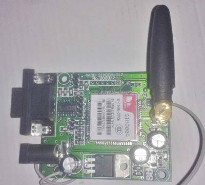
The SIM900 is a complete Quad-band GSM/GPRS Module which delivers GSM/GPRS 850/900/1800/1900MHz performance for voice, SMS and Data with low power consumption.
Circuit Description
Connections of this GSM Based Home Automation Circuit are quite simple, here a liquid crystal display is used for displaying status of home appliances which is directly connected to arduino in 4-bit mode. Data pins of LCD namely RS, EN, D4, D5, D6, D7 are connected to arduino digital pin number 6, 7, 8, 9, 10, 11. And Rx and Tx pin of GSM module is directly connected at Tx and Rx pin of Arduino respectively. And GSM module is powered by using a 12 volt adaptor. 5 volt SPDT 3 relays are used for controlling LIGHT, FAN and TV. And relays are connected to arduino pin number 3, 4 and 5 through relay driver ULN2003 for controlling LIGHT, FAN and TV respectively.

Code Description
In programming part of this project, first of all in programming we includes library for liquid crystal display and then we defines data and control pins for LCD and home appliances.
#include<LiquidCrystal.h>
LiquidCrystal lcd(6,7,8,9,10,11);

#define Fan 3
#define Light 4
#define TV 5

int temp=0,i=0;
int led=13;
After this serial communication is initialized at 9600 bps and gives direction to used pin.
void setup()
{
  lcd.begin(16,2);
  Serial.begin(9600);
  pinMode(led, OUTPUT);
   pinMode(Fan, OUTPUT);
    pinMode(Light, OUTPUT);
     pinMode(TV, OUTPUT);
For receiving data serially we have used two functions one is Serial.Available which checks whether any serial data is coming and other one is Serial.Read which reads the data that comes serially.
 while (Serial.available())
      {
      char inChar=Serial.read();
After receiving data serially we have stored it in a string and then waiting for Enter.
void serialEvent()
 {
  while(Serial.available())
  {
    if(Serial.find("#A."))
    {
      digitalWrite(led, HIGH);
      delay(1000);
      digitalWrite(led, LOW);
      while (Serial.available())
      {
      char inChar=Serial.read();
      str[i++]=inChar;
      if(inChar=='*')
      {
        temp=1;
        return;
      }
When Enter comes program start to compare received string with already defined string and if string matched then a relative operation is performed by using appropriate command that are given in code.
void check()
{
   if(!(strncmp(str,"tv on",5)))
    {
      digitalWrite(TV, HIGH);
      lcd.setCursor(13,1);
      lcd.print("ON    ");
      delay(200);
    }

   else if(!(strncmp(str,"tv off",6)))
    {
      digitalWrite(TV, LOW);
      lcd.setCursor(13,1);
      lcd.print("OFF    ");
      delay(200);
    }
Code
#include<LiquidCrystal.h>
LiquidCrystal lcd(6,7,8,9,10,11);
#define Fan 3
#define Light 4
#define TV 5
int temp=0,i=0;
int led=13;
char str[15];
void setup()
{
lcd.begin(16,2);
Serial.begin(9600);
pinMode(led, OUTPUT);
pinMode(Fan, OUTPUT);
pinMode(Light, OUTPUT);
pinMode(TV, OUTPUT);
lcd.setCursor(0,0);
lcd.print(“GSM Control Home”);
lcd.setCursor(0,1);
lcd.print(” Automaton “);
delay(2000);
lcd.clear();
lcd.print(“Circuit Digest”);
delay(1000);
lcd.setCursor(0,1);
lcd.print(“System Ready”);
Serial.println(“AT+CNMI=2,2,0,0,0”);
delay(500);
Serial.println(“AT+CMGF=1”);
delay(1000);
lcd.clear();
lcd.setCursor(0,0);
lcd.print(“Fan Light TV “);
lcd.setCursor(0,1);
lcd.print(“OFF OFF OFF “);
}
void loop()
{
lcd.setCursor(0,0);
lcd.print(“Fan Light TV”);
if(temp==1)
{
check();
temp=0;
i=0;
delay(1000);
}
}
void serialEvent()
{
while(Serial.available())
{
if(Serial.find(“#A.”))
{
digitalWrite(led, HIGH);
delay(1000);
digitalWrite(led, LOW);
while (Serial.available())
{
char inChar=Serial.read();
str[i++]=inChar;
if(inChar==’*’)
{
temp=1;
return;
}
}
}
}
}
void check()
{
if(!(strncmp(str,”tv on”,5)))
{
digitalWrite(TV, HIGH);
lcd.setCursor(13,1);
lcd.print(“ON “);
delay(200);
}
else if(!(strncmp(str,”tv off”,6)))
{
digitalWrite(TV, LOW);
lcd.setCursor(13,1);
lcd.print(“OFF “);
delay(200);
}
else if(!(strncmp(str,”fan on”,5)))
{
digitalWrite(Fan, HIGH);
lcd.setCursor(0,1);
lcd.print(“ON “);
delay(200);
}
else if(!(strncmp(str,”fan off”,7)))
{
digitalWrite(Fan, LOW);
lcd.setCursor(0,1);
lcd.print(“OFF “);
delay(200);
}
else if(!(strncmp(str,”light on”,8)))
{
digitalWrite(Light, HIGH);
lcd.setCursor(7,1);
lcd.print(“ON “);
delay(200);
}
else if(!(strncmp(str,”light off”,9)))
{
digitalWrite(Light, LOW);
lcd.setCursor(7,1);
lcd.print(“OFF “);
delay(200);
}
else if(!(strncmp(str,”all on”,6)))
{
digitalWrite(Light, HIGH);
digitalWrite(Fan, HIGH);
digitalWrite(TV, HIGH);
lcd.setCursor(0,1);
lcd.print(“ON ON ON “);
delay(200);
}
else if(!(strncmp(str,”all off”,7)))
{
digitalWrite(Light, LOW);
digitalWrite(Fan, LOW);
digitalWrite(TV, LOW);
lcd.setCursor(0,1);
lcd.print(“OFF OFF OFF “);
delay(200);
}
}