This post shows how to build a weather station using ESP8266 NodeMCU development board (ESP12-E module) and BME280 barometric pressure, temperature & humidity sensor.
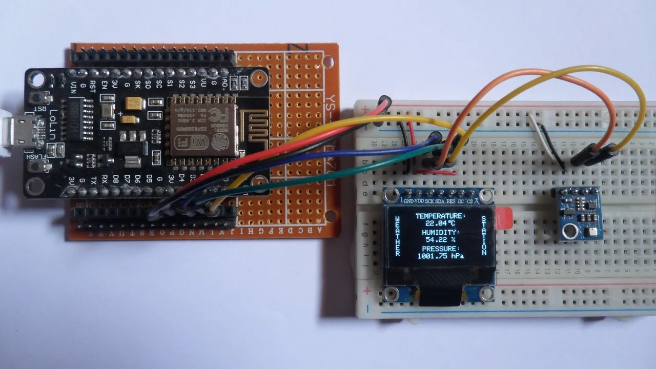
The NodeMCU reads temperature & humidity & pressure values from the BME280 sensor and prints them (respectively in °C & RH% & hPa) on SSD1306 OLED display (128×64 pixel).
About The BME280 Sensor:
The BME280 sensor from Bosch Sensortec is a low cost digital pressure, temperature and humidity sensor with good accuracy. Because pressure changes with altitude we can use it as an altimeter with ±1 meter accuracy (pressure accuracy = ±1 hPa). Some parameters of the sensor are listed below:
Pressure range: 300 … 1100 hPa (equivalent to +9000…-500m above/below sea level)
Pressure resolution: 0.01 hPa ( < 10 cm)
Temperature range: -40 … 85 °C
Temperature resolution: 0.01 °C
Humidity range: 0 … 100 %
Interface: I2C and SPI
Supply voltage range: 1.71 … 3.6 V
In this project the BME280 sensor is used in I2C mode.
The SSD1306 OLED display used in this project is configured to work in I2C mode, some SSD1306 OLED boards may require a small hardware modifications (to select between SPI mode and I2C mode) such as soldering, placing jumpers …
To see how to interface ESP8266 NodeMCU with SSD1306 OLED display, visit the following post:
Interfacing ESP8266 NodeMCU With SSD1306 OLED
Hardware Required:
- ESP8266 NodeMCU development board
- SSD1306 OLED display with 128×64 pixel resolution
- BME280 sensor module —-> Datasheet
- micro USB cable (for programming and powering the circuit)
- Breadboard
- Jumper wires
NodeMCU with BME280 sensor SSD1306 OLED circuit:
Project circuit schematic diagram is shown below.
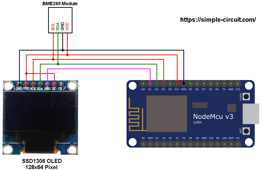
Generally, the BME280 Sensor module has at least 4 pins because it can work in SPI mode or I2C mode. For the I2C mode we need 4 pins: VCC, GND, SDA and SCL where:
GND (ground) is connected to NodeMCU GND pin,
VCC is the supply pin which is connected to NodeMCU 3V3 pin,
SDA is I2C bus serial data line, connected to NodeMCU pin D2 (GPIO4),
SCL is I2C bus serial clock line, connected to NodeMCU pin D3 (GPIO0).
The SSD1306 OLED Display is connected to the NodeMCU board as follows:
SSD1306 OLED GND goes to NodeMCU GND pin,
SSD1306 OLED VDD to NodeMCU 3V3,
SSD1306 OLED SDA pin (serial data) to NodeMCU pin D2 (GPIO4),
SSD1306 OLED SCK pin (serial clock) to NodeMCU pin D3 (GPIO0),
SSD1306 OLED RES pin (reset) to NodeMCU pin D1 (GPIO5).
The SSD1306 OLED display DC pin is connected to VDD (3.3V) which means I2C slave address of the device is 0x3D. If the DC pin is connected to ground (GND) then the I2C slave address becomes 0x3C.
The SSD1306 OLED and the BME280 sensor are connected to the same I2C bus (slave devices).
The I2C slave address of the SSD1306 OLED differs from the one of the BME280 sensor, this difference allows the master device (ESP8266EX microcontroller) to talk to one of them (only one at a time).
NodeMCU with BME280 sensor SSD1306 OLED code:
The following Arduino code requires 3 libraries from Adafruit Industries:
The first library is a driver for the SSD1306 OLED display which can be installed from Arduino IDE library manager (Sketch —> Include Library —> Manage Libraries …, in the search box write “ssd1306” and install the one from Adafruit).
The second library is Adafruit graphics library which can be installed also from Arduino IDE library manager.
The third library is for the BME280 sensor.
The previous 3 libraries can also be installed manually, download links are below:
Adafruit SSD1306 OLED Driver —-> Direct Link
Adafruit Graphics Library —-> Direct Link
Adafruit BME280 Library —-> Direct Link
You may need to install the Adafruit Unified Sensor library if it’s not already installed, download link is below:
Adafruit Unified Sensor Library —-> Direct Link
After the download, go to Arduino IDE —> Sketch —> Include Library —> Add .ZIP Library … and browse for the .zip file (previously downloaded).
The same thing for the other library files.
The 3 libraries are included in the code as:C
| #include <Adafruit_GFX.h> // include Adafruit graphics library #include <Adafruit_SSD1306.h> // include Adafruit SSD1306 OLED display driver #include <Adafruit_BME280.h> // include Adafruit library for BME280 sensor |
Definition of the SSD1306 OLED reset pin (RES) and initialization of its library are as shown below:C
| // define SSD1306 OLED reset at ESP8266 GPIO5 (NodeMCU D1) #define OLED_RESET 5 // initialize Adafruit display library Adafruit_SSD1306 display(OLED_RESET); |
As any other I2C device, the BME280 sensor has an I2C slave address which may be 0x76 or 0x77. This address depends on the connection of the SDO pin (used for SPI mode as serial data out or MISO), if the SDO pin is connected (directly or through resistor) to VCC (3.3V) the address will be 0x77, and if it’s connected to GND the address will be 0x76.
The default I2C address of the BME280 library is defined as 0x77 and my device I2C address is 0x76.
In the code, the definition of the I2C slave address and the initialization of its library are shown below:C
| // define device I2C address: 0x76 or 0x77 (0x77 is library default address) #define BME280_I2C_ADDRESS 0x76 // initialize Adafruit BME280 library Adafruit_BME280 bme280; |
The initialization of the BME280 sensor is done using the function begin() which returns 1 if OK and 0 if error. In the code the initialization with the previously defined address is as shown below:C
| bme280.begin(BME280_I2C_ADDRESS) |
Reading the values of temperature and pressure is done as shown below:C
| // read temperature, humidity and pressure from the BME280 sensor float temp = bme280.readTemperature(); // get temperature in degree Celsius float humi = bme280.readHumidity(); // get humidity in rH% float pres = bme280.readPressure(); // get pressure in Pa |
Note that the BME280 sensor library returns the value of the pressure in Pa unit and to convert it to hPa we’ve to divide it by 100.
1 bar = 10000 Pa = 100 hPa. ( 1 hPa = 100 Pa = 1 millibar)
Pa: Pascal
hPa: hectoPascal
Temperature, humidity and pressure values are displayed on the SSD1306 OLED screen.
If there is a problem with the BME280 sensor (for example wrong device address) the screen will display Connection Error.
Full Arduino Code:
The following picture shows my simple hardware circuit:
