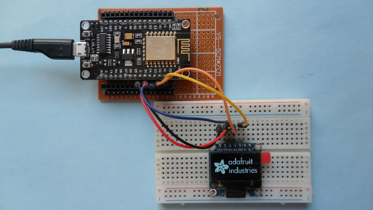
This topic shows how to interface the SSD1306 OLED display with ESP8266 NodeMCU development board (ESP-12E). The display used in this project has a resolution of 128×64 Pixel and works in I2C mode, that means the NodeMCU communicates with the display using I2C communication protocol. The I2C protocol uses two lines: SDA (serial data) and SCL (serial clock). the SSD1306 requires 2 pins for the I2C bus and an additional reset pin (if the SSD1306 OLED board has a reset pin).
SSD1306 OLED driver for Arduino IDE:
Adafruit Industries provides a very nice library for the SSD1306 OLED, it can be easily installed using Arduino library manager (Sketch —> Include Library —> Library Manager), or manually by downloading it from the link below and adding it to Arduino libraries folder (C:\Program Files\Arduino\libraries):
Adafruit SSD1306 OLED Library
Note that the Adafruit SSD1306 OLED driver supports 3 types: 128×64, 128×32 and 96×16 pixel, we can select between them in the driver header file Adafruit_SSD1306.h. Opening the file with a text editor such as the Arduino IDE gives (scroll down as shown):
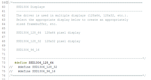
I commented the default display type #define SSD1306_128_32 and uncommented #define SSD1306_128_64 because I’m using 128×64 pixel display (0.96″).
We need an other library named Adafruit GFX (graphics library) which can be installed through Arduino library manager or manually by downloading it from the link below:
Adafruit GFX Library

Hardware Required:
The components listed below are required for this project.
- ESP8266 NodeMCU module (ESP-12E)
- SSD1306 OLED display
- Breadboard
- Jumper wires
NodeMCU interfacing with SSD1306 OLED circuit:
The following image shows the circuit schematic diagram of the project.

and the second image shows Fritzing breadboard circuit:
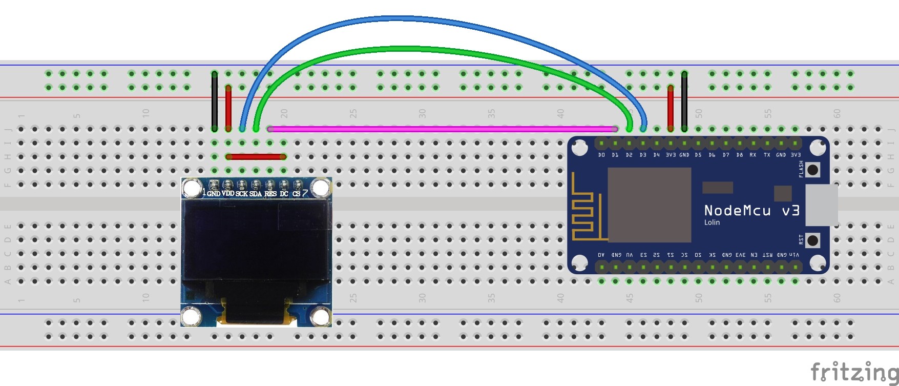
The SDA and SCL lines of the I2C bus come from GPIO4 (D2) and GPIO0 (D3) of the NodeMCU board (respectively), they are connected to SDA and SCL (SCK) pins of the SSD1306 display module.
Reset pin (RES) of the display module is connected to GPIO5 (D1) of the NodeMCU development board.
The SSD1306 display module is supplied with 3.3V which comes from the NodeMCU board.
NodeMCU interfacing with SSD1306 OLED code:
Project code is Adafruit library example code (ssd1306_128x64_i2c) with minor modifications. I added Wire.begin(4, 0); to configure the I2C bus pins. SDA is set to GPIO4 (D2) and SCL to GPIO0 (D3). The reset pin of the display module is connected to pin GPIO5 (D5):
#define OLED_RESET 5
The default clock frequency is 100kHz, for 400kHz clock uncomment line number 65 (L for long):
//Wire.setClock(400000L);
Full Arduino code: